Restoration of Jordán retention reservoir
Project name
Restoration of Jordán retention reservoir – stage 1: bottom outlet
Project owner
Tábor municipality
Contractor
Consortium of Daich, spol. s r.o. & Metrostav a.s. D6 & Zvonovec, a.s.
Designer
Detailed design for bottom outlet: Ko-ka s.r.o.
Contractor for geotechnical monitoring
Vodní díla – TBD, a.s. & ARCADIS Geotechnika, a.s.
Construction period
02/2012 - 07/2014
Technical description
Construction purpose
Jordán valley reservoir is the first reservoir in Central Europe developed for supplying a town with water. The origination of the historic Jordán reservoir on the Tismenice Brook was mentioned in historical sources in 1492. The reservoir has an earthfill dam nearly 20 m high, with a very steep slope of the downstream face. The dam crown has already for a long time been an important, very busy and hard to replace traffic artery connecting two parts of the town of Tábor. Jordan reservoir was used for fish breeding purposes. Jordan fish harvesting events were the most frequent opportunities for opening the bottom outlet used for emptying the reservoir. The outlet facility was used for fish harvesting for the last time in 1830. After this date the reservoir has never again been emptied and the wooden outlet tubes have probably got gradually mudded up and devastated. The location of these tubes is unknown and their restoration is not realistic. Installing a new bottom outlet through the dam body when the reservoir is not empty would be very risky, first of all for the overall stability and sealing capacity of the dam. This means that at the moment it cannot be emptied. In 2002 the town of Tábor was affected by flooding and was added to the list of structurally affected regions. It was one of the reasons why in 2004 the Tábor municipality commenced the work on the preparation of the project named “Restoration of Jordán retention reservoir – Stage 1: Bottom outlet”, which is an important operating element of the dam as well as an element required for ensuring its safety, first of all during floods or critical and extraordinary situations and, in addition, for the project stage 2 the aim of which is dredging of Jordán reservoir, reducing the trophical load, improving the quality of water and expanding the retention space. The purpose of the project as a whole is to provide a bottom outlet of Jordán reservoir in Tábor. The outlet construction comprises cut-and-cover and mined structures, which will eventually divert water from the reservoir to the Tismenice Brook valley. This diversion will be ensured by the following civil engineering structures:
SO 01 – intake pressure tunnel with the intake structure,
SO 02 – outlet gate structure,
SO 03 – pressure-less outlet tunnel with a portal,
SO 04 – open channel in the reservoir bottom.
The bottom outlet is designed as a linear structure, mostly running underground, which makes the emptying of the reservoir from its deepest point through a by-pass running behind the dam embedment into the right-hand bank possible, with the final discharge to the Tismenice Brook located on the right side of the safety spillway. The work on the bottom outlet had to be coordinated with activities required for the pumping of water from the reservoir.
Project location
The portal of the pressure-less outlet tunnel is located in the rock mass in which the dam is embedded in the Tismenice Brook bottom, on the right side of the safety spillway of Jordán reservoir, and the tunnel is connected to the existing brook channel through a portal. The pressure-less tunnel is 148.77 m long. It ends in SO 2 Outlet Gate structure (by a shaft sunk from the upstream side of the dam). SO1 mined pressure tunnel structure is connected to the outlet gate. It is 26.6 m long and ends by a 14.2 m long cut-and-cover part and the intake structure. Owing to the depth of the structures, no utility networks were directly affected. The tunnel route is crossed by all networks common within a street profile, i.e. water lines, sewers, gas mains and communication cables. All of these networks are located at the distance of 15 m above the tunnel crown as the minimum. They were not damaged by the activities carried out in a mining-like way. The excavation for the outlet gate structures and the work on the cut-and-cover and mined parts of the pressure tunnel and the intake structure proceeded concurrently with the excavation of the pressure-less tunnel. The final lining has been completed in the pressure-less tunnel, to be followed by the final lining of the outlet gate structures and the pressure tunnel connecting to the intake structure.
Geological conditions
The geological composition is highly variable – the bedrock, in which geological layers and their mechanical properties frequently alternate, is found under an about 3-4 m thick layer of made-ground and loams. Syenites, diorites, paragneiss and granites were encountered during the tunnel excavation. The tunnel excavation encountered several tectonic zones and the small to extremely small spacing of joints with mechanical properties changing on their contacts. Discontinuity surfaces were covered with limonite and coated with dark-green chlorite, Fe oxides and vein quartz. According to the survey the rocks exhibit limonitic coats on fissures. The faults were filled with hydrothermally deteriorated rocks, vein quartz, sandy gouge with slaking clay. The rock classes reached the levels of R2 – R3, even R4 in faults.
Hydrogeological conditions
Inflows from fissures varied from dripping up to local inflows of 2 l/s. Stronger inflows were registered during the work on the outlet gate structures and the pressure tunnel, where they reached up to 120 l/s when the excavation was approaching the reservoir bottom; bursts of inflows from probe holes drilled in the advance core of the pressure tunnel reached up to 300 l/s (90 l/s after settling).
NATM excavation support classes for pressure-less tunnel
The excavation of the pressure-less tunnel was divided into 3 NATM excavation support classes, depending on geological conditions encountered and the results of geotechnical monitoring. The excavation support was changed from KARI mesh with a 100 mm thick layer of C20/25 shotcrete through BTX lattice girders to Toussaint-Heintzmann steel arches. Self-drilling spiles driven into the arch and radial anchors were also part of the primary support. The excavation advance round length varied from 0.7 m to 2.0 m. The excavation for the outlet gate structure was supported by I240 frames, KARI mesh and a 150 mm thick layer of shotcrete, locally even rockbolts.
Selection of technology and realisation of the primary lining of the pressure-free tunnel
An overhead loader NL 12 on a 600 mm undercarriage, loading muck on 0.63 m3 mine cars was employed for the face excavation. Rails were laid from the portal, with one passing bay within the route length and one at the portal. Muck from full cars was emptied into containers placed on the embankment wall using an AD 20T crane. Blast holes were drilled with VK-22 hand-held drills using VP800 jacklegs. Profiling was carried out either by contour blasting (depending on the rock hardness) or, exceptionally, with pick hammers. Silos for MAXIT pre-mixed dry shotcrete mixture, an AL-252 spraying machine and an Atmos 1000 SE compressor were installed at the portal for the purpose of the application of shotcrete. A Dn65 pipeline leading to the excavation face was provided in the tunnel. The ventilation system consisted of metal Spiro ducts and an APXE400 fan. The tunnel was driven uphill; mine water was drained by gravity, flowing through the rail track ballast to sumps in the tunnel and proceeded through a pipeline to a sludge pit located at the portal. Then it was discharged to the Tismenice Brook. Eurodyn 2000 explosives and Exel LP non-electric detonators were used for blasting operations. Depending on the geology encountered, 40 blast holes were drilled in average for a 1 m long excavation round. They were charged with 16 kg of explosives. The execution of blasting was restricted to the time from 7 a.m. to 10 p.m. The work carried out during night shifts comprised extending the media distribution lines, rails and ventilation ducts, applying shotcrete and drilling blastholes. The tunnelling work started from the treated bottom of the Tismenic Brook by forming a canopy, protecting the workplace against water discharged from the reservoir safety spillway, and a concrete canopy of the tunnel itself protecting persons against rock debris falling from the exposed rock slope above the portal. Owing to the pre-portal canopy it was possible to install a protective barrier consisting of a steel element of a trench box protected with tyres cut into pieces. It protected the portal surroundings against debris spraying the area after blasting. The barrier was used until the excavation face reached the tunnel chainage of 35 m, where the face got behind a horizontal curve. The work operations were several times interrupted because of intense discharging of water from the reservoir over the safety spillway after heavier rain inundated the rail track in front of the portal.
The shaft was sunk from a cutting in the reservoir bank, using blasting. Muck was loaded at the face on mine cars and lifted to the surface by an RDK 300 crane. The other technology was identical with that applied to driving of tunnels.
Probe holes drilled in the pressure tunnel advance core encountered significant water inflows. For that reason pre-excavation grouting into the advance core was carried out.
The final lining of the tunnels consisted of C30/37 water retaining concrete without waterproofing, with steel sheet waterbars installed in construction joints provided with crystallising coating. Expansion joints were provided with PVC waterbars. Steel bars and KARI mesh were used for the concrete reinforcement.
The concrete lining was 300 mm thick. The concrete casting process was divided into two stages: the casting of the bottom with concrete stubs on the sides cast behind formwork, and the second stage comprising the casting of the vault, also behind steel formwork. Grout was injected above the crown of the finished lining and was provided wit final crystallising coating.
Geotechnical monitoring
The geotechnical monitoring comprised the observation of the stability of both the upstream and downstream faces of the Jordán dam, relative convergences of the tunnel lining on 3-point measurement profiles, measurements of the terrain surfaces by surveying, monitoring of existing buildings on the surface threatened by the underground excavation, and geological face mapping. The values of deformations measured within the framework of the monitoring varied within the limits expected in the detailed design. No existing buildings and structures were endangered.
Construction history:
02/2012 – 05/2012 primary lining of pressure-less tunnel SO 03
03/2012 – 07/2012 primary lining of outlet gate structure SO 02
08/2012 – 10/2012 primary lining of pressure tunnel SO 01
06/2012 – 09/2012 secondary lining of pressure-less tunnel SO 03
12/2012 – 02/2013 secondary lining of pressure tunnel SO 01
The secondary lining of outlet gate structure is not part of the Metrostav D1 contract.
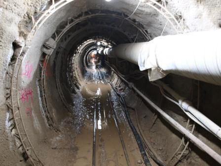
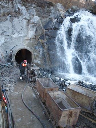
Pressure-less tunnel with NL12 loader
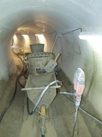
Final bottom casting in pressure-less tunnel
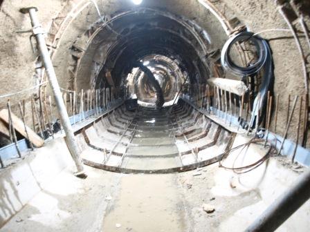
Formwork for casting the vault and sidewalls in pressure-less tunnel
Injecting grout above the crown after the casting of vaults
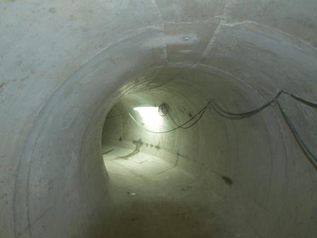
Final lining of pressure-free tunnel
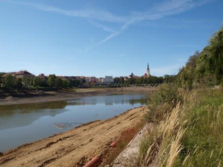
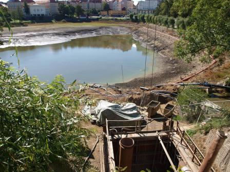
Emptying the Jordán reservoir
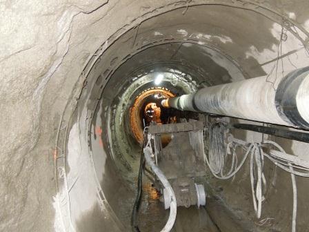
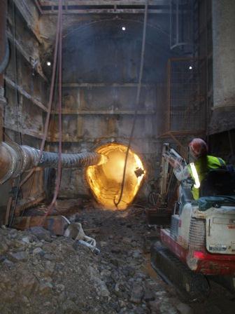
Driving the pressure tunnel from the outlet gate structure
Sinking the outlet gate shaft
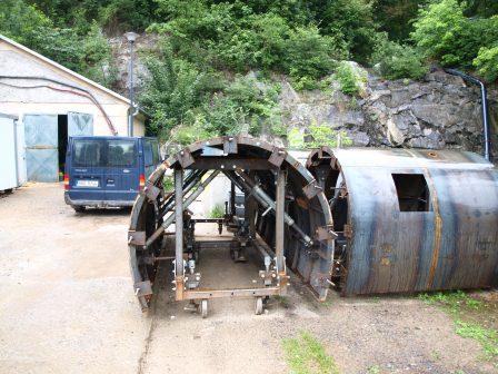
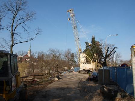
Construction facility for sinking the outlet gate shaft
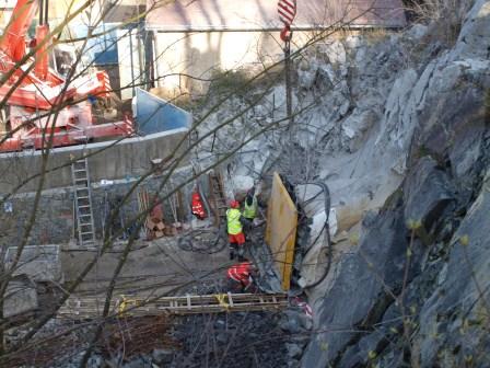
Protective barrier in front of tunnel mouth before blasting
Passing bay in front of the pressure-free tunnel
Pressure-free tunnel provided with a primary lining