
The Votice, Olbramovice, Zahradnice and Tomice I ,II Tunnels
MODERNISATION OF THE VOTICE-BENEŠOV U PRAHY RAIL LINE section
The Votice, Olbramovice, Zahradnice and Tomice I and II tunnels
Project owner:
Railway Infrastructure Administration, state organisation
Contractors:
for the Olbramovice, Zahradnice and Tomice I and IItunnels:
Sdružení VoBen consortium
EUROVIA CS, a. s. – consortium leader
Subterra a. s. – for the Olbramovice, Zahradnice, Tomický I and II tunnels
Viamont DSP, a. s.
for the Votice tunnel:
Hochtief CZ a.s.
Designer:
General designer
SUDOP Praha a. s.
IKP Consulting Engineers s.r.o. – for the Votice, Olbramovice and Tomice I tunnels
Metroprojekt Praha a. s. – for the Zahradnice tunnel
Sudop Praha a. s. – for the Tomice II tunnel
Designers for detailed design
IKP Consulting Engineers s.r.o. – for the Votice, Olbramovice and Tomice I tunnels
Metroprojekt Praha a.s. – for the Zahradnice tunnel
Sudop Praha a.s. – for the Tomice II tunnel
Contractor for geotechnical monitoring
ARCADIS Geotechnika a.s.
Construction period:
08/2009 – 12/2013
Technical data:
|
|
2.690 km |
|
Mined part in total |
1.716 km |
|
Cut-and-cover part in total |
0.974 km |
|
Groundwork volume in total |
2,310,618 m3 |
Mined tunnels
The Olbramovice tunnel
The total length of 480m (360m long mined part) with cut-and-cover pre-portal sections (2 x 60m). The overburden height ranging from about 6m to 20m.
Worse engineering geological conditions than the conditions anticipated by the survey were encountered during the tunnel excavation. R4-R5 class (up to R3 in the middle of the massif), relatively intensely weathered and tectonically disturbed gneiss with applitic granite and graphitic schist interbeds were encountered instead of the predicted relatively good quality granitic rocks. The high frequency of discontinuities caused problems with the stability of unsupported excavation; the rock disintegrated into gravel and fell from the excavation face and roof. This was why relatively short excavation rounds, varying from 1.0 to 1.5m, had to be used, together with the corresponding robust support designed for excavation support classes IV, V and VI.
The primary support consists of a shotcrete lining reinforced with lattice girders and welded mesh, SN-type resin-encapsulated anchors and hydraulically expanded rock bolts. The application of the support elements corresponds to the respective NATM excavation support class. The excavation support classes provide basic definitions of elements of the excavation support; if necessary, they are further modified on the basis of results of geotechnical measurements conducted during the course of the works.
The secondary (final) lining in the mined tunnel section is in cast-in-situ reinforced concrete, the minimum thickness is 350mm. It is designed to secure long-term stability of the tunnel throughout its design life (100 years). Results of the geotechnical monitoring will provide a basis for deciding on the extent of the use of unreinforced concrete for the lining. The secondary lining casting is divided into 12m-long blocks; a traveller form is used. The minimum thickness of the lining in the cut-and-cover tunnel section in the crown is 600mm, increasing in the direction toward the springing.
The waterproofing class “O”, prescribed by the TKP 20 Technical Specification, will be provided in the mined tunnel sections by means of an intermediate waterproofing membrane (2mm thick PVC membrane with a signal layer) installed on the circumference of the upper vault (the umbrella-type system). It will be protected against damaging due to irregularities of the primary lining surface by a geotextile layer. Water will flow down the membrane and will be directed to the footing of the vault, where a side-wall drain with a flat bottom will be located. The cut-and-cover sections of the tunnel are designed in seepage resistant concrete, with construction joints between casting blocks sealed by ribbed PVC waterstops. The longitudinal gradient (9-10.5 per mille) allows the tunnel drainage to run along the tunnel sides, with water flowing up to the tunnel exit portal. The tunnel drainage gradient is designed to be identical with the gradient of the rail track. A manhole allowing the side-wall drainage to be cleaned is located in every other safety recess (spaced at 48m). Contingent seepage through the tunnel bottom is evacuated to an external drain through the central drain.
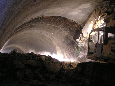
The Olbramovice tunnel – initial round of the top heading excavation from the entrance portal
The Olbramovice tunnel – instable excavation face
The Zahradnice tunnel
The length of 1,044m (mined part 936m long), cut-and-cover pre-portal sections (southern and northern cut-and-cover parts 48m and 60m long, respectively). The overburden height ranging from about 4m to 25m).
The tunnel excavation has encountered good quality, weakly weathered, Sedlčany-type biotite-amphibolitic granite categorised as strength classes R1 – R2. It corresponds to results of the engineering geological survey. Owing to the relatively favourable geology it is possible to use subtle support classes III and II with the round length ranging from 2.0 to 2.5m. The favourable geological structure is from time to time disturbed by tectonic faults, which manifest themselves by more pronounced fracturing of the rock mass, limonitised discontinuity surfaces and higher (locally concentrated) inflows of water.
The primary support consists of a sprayed concrete lining with lattice girders, welded mesh and hydraulically expanded rock bolts. Canopy tube pre-support 12m and 10m long is used to stabilise the top heading at the exit and entry portals, respectively. Elements of the excavation support are applied in compliance with requirements of the respective NATM excavation support classes. The excavation support classes provide basic definitions of elements of the excavation support; if necessary, they are further modified on the basis of results of geotechnical measurements conducted during the course of the works.
The secondary (final) lining in the mined tunnel section is in cast-in-situ reinforced concrete, the minimum thickness is 350mm. It is designed to secure long-term stability of the tunnel throughout its design life (100 years). Results of the geotechnical monitoring will provide a basis for deciding on the extent of the use of unreinforced concrete for the lining. The secondary lining casting is divided into 12m-long blocks; a traveller form is used. The minimum thickness of the lining in the cut-and-cover tunnel section in the crown is 600mm, increasing in the direction toward the springing.
The waterproofing class “O”, prescribed by the TKP 20 Technical Specification, will be provided in the mined tunnel sections by an intermediate waterproofing membrane (2mm thick PVC membrane with a signal layer) installed on the circumference of the upper vault (the umbrella-type system). It will be protected against damaging due to irregularities of the primary lining surface by a geotextile layer. Water will flow down the membrane and will be directed to the footing of the vault, where a side-wall drain with a flat bottom will be located. The cut-and-cover sections of the tunnel are designed in seepage resistant concrete, with construction joints between casting blocks sealed by ribbed PVC waterstops. The longitudinal gradient (9-10.5 per mille) allows the tunnel drainage to run along the tunnel sides, with water flowing up to the tunnel exit portal. The tunnel drainage gradient is designed to be identical with the gradient of the rail track. A manhole allowing the side-wall drainage to be cleaned is located in every other safety recess (spaced at 48m). Contingent seepage through the tunnel bottom is evacuated to an external drain through the central drain.
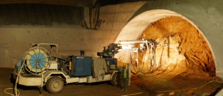
The Zahradnice tunnel – commencement of the top heading excavation
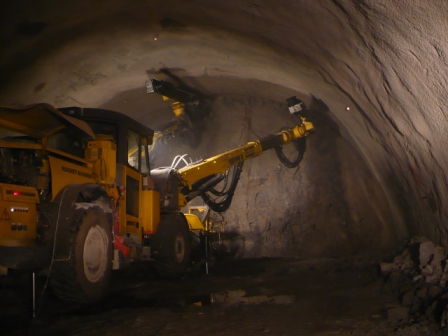
The Zahradnice tunnel – drilling operations (Boomer E2C)
The Tomice I and II tunnels
The total length of the Tomice I tunnel is 324m (216m long mined part) with cut-and-cover pre-portal sections (60m and 48m long). The overburden height ranges from about 6m to 15m. The total length of the Tomice II tunnel is 252m (204m long mined part) with cut-and-cover pre-portal sections (2 x 24m). The overburden height ranges from about 6m to 11m.
The geological structure at the Tomice I tunnel was worse than anticipated by the engineering-geological survey. The quality-related characteristics of the rock mass roughly corresponded to the anticipation, but geomechanical properties of the rock encountered by the excavation were worse. Lower quality metamorphites (migmatitised up to granitised gneiss passing locally to migmatite) were accompanied by plutonic, aligned-texture granodiorites to diorites, intrusions of finely grained haplites and pinkish finely- to medium-grained vein granite. Despite the fact that the classification of the plutonite igneous rocks corresponded to the strength up to R2 (R4 – R5 in more weathered parts), the combination with lower-quality gneiss and the high frequency of discontinuities led to reduced stability of the excavation. Falling of rock blocks from the unsupported excavation surface, blocky disintegration of rock and opened, smooth discontinuities filled with clay or limonite did not allow longer excavation rounds to be used (1.0 – 2.0m long) – excavation support classes IV and V prevail, class II is the maximum locally, in advantageous conditions.
The Tomice II tunnel excavation has just started; the initial metres suggest that the engineering geological conditions will be worse than expected.
The primary support consists of a shotcrete lining reinforced with lattice girders and welded mesh, SN-type resin-encapsulated anchors and hydraulically expanded rock bolts. Canopy tube pre-support 10m long is used on both sides of the Tomice II portals to stabilise the top heading. The application of the support elements corresponds to the respective NATM excavation support class. The excavation support classes provide basic definitions of elements of the excavation support; if necessary, they are further modified on the basis of results of geotechnical measurements conducted during the course of the works.
The secondary (final) lining in the mined tunnel section is in cast-in-situ reinforced concrete, the minimum thickness is 350mm. It is designed to secure long-term stability of the tunnel throughout its design life (100 years). Results of the geotechnical monitoring will provide a basis for deciding on the extent of the use of unreinforced concrete for the lining. The secondary lining casting is divided into 12m-long blocks; a traveller form is used. The minimum thickness of the lining in the cut-and-cover tunnel section in the crown is 600mm, increasing in the direction toward the springing.
The waterproofing class “O”, prescribed by the TKP 20 Technical Specification, will be provided in the mined tunnel sections by an intermediate waterproofing membrane (2mm thick PVC membrane with a signal layer) installed on the circumference of the upper vault (the umbrella-type system). It will be protected against damaging due to irregularities of the primary lining surface by a geotextile layer. Water will flow down the membrane and will be directed to the footing of the vault, where a side-wall drain with a flat bottom will be located. The cut-and-cover sections of the tunnel are designed in seepage resistant concrete, with construction joints between casting blocks sealed by ribbed PVC waterstops. The longitudinal gradient (10 per mille) allows the tunnel drainage to run along the tunnel sides, with water flowing up to the tunnel exit portal. The tunnel drainage gradient is designed to be identical with the gradient of the rail track. A manhole allowing the side-wall drainage to be cleaned is located in every other safety recess (spaced at 48m). Contingent seepage through the tunnel bottom is evacuated to an external drain through the central drain.
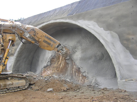
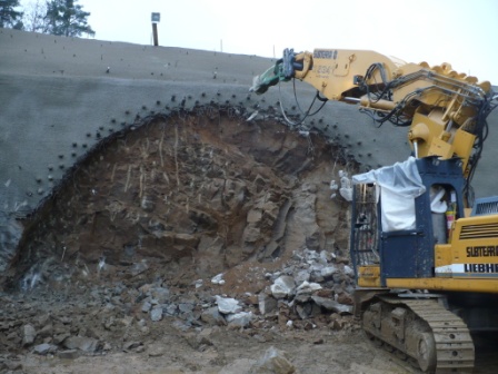
The Tomice I tunnel – mechanical disintegration of the initial metre of the tunnel (Liebherr 944)
The Tomice I tunnel – the tunnel top heading breakthrough (Liebherr 944)
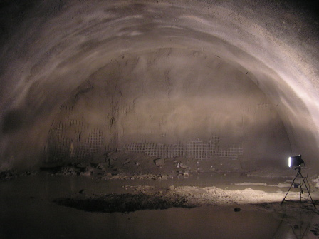
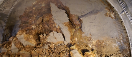
The Tomice II tunnel – top heading face after completion of 20m of excavation
The Votice cut-and-cover tunnel
The 590m long Votice tunnel is the longest cut-and-cover railway tunnel in the Czech republic. The construction proceeds from the Prague exit portal toward the Budějovice entry portal. The total groundwork volume amounts to 150,000m3 (granitic rock of various degrees of weathering prevails). The maximum depth of the sloped construction trench is 20m.
The concrete casting blocks are 10m long. One concrete block is reinforced with 18t of steel bars. The reinforcement becomes self-supporting after the assembly. This reinforcement installation technique is better known from mined tunnels. Nevertheless, it had to be applied in the case of the Votice tunnel taking into consideration the optimal use of the double-sided traveller formwork in terms of time. Significant losses of time would originate if the classical reinforcement installation technique had been used (3 days for the installation in one block). Taking into consideration the fact that the concrete casting operations are planned for a winter season, the contractor expects that a travelling gantry securing thermal insulation along the lining circumference will be used after stripping the form to mitigate the temperature shock.
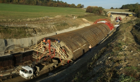
The Votice tunnel – self-supporting reinforcement for the cut-and-cover tunnel
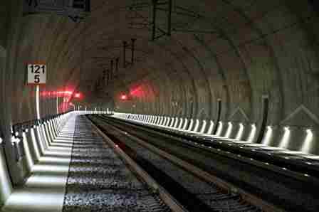
The Votice, Olbramovice, Zahradnice and Tomice I and II tunnels were put into operation on 30.11. 2012.

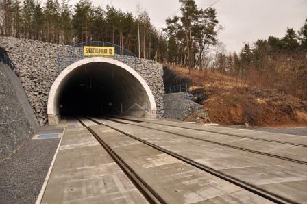
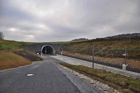
The Olbramovice tunnel- entrance portal
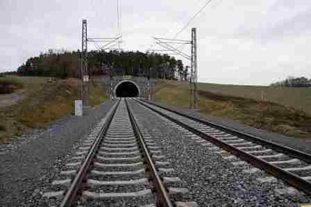
The Tomice II tunnel- entrance portal
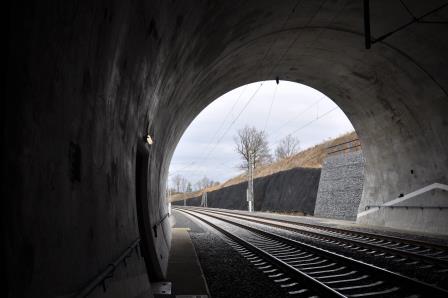
The Tomice II tunnel- exit from the tunnel
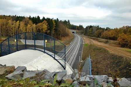
View from the Tomice tunnel to the Tomice II tunnel

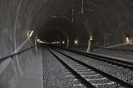
Exit from theTomice to Tomice I tunnel
The Votice tunnel
The Votice tunnel - exit portal
The Zahradnice tunnel
The Zahradnice tunnel - entrance portal