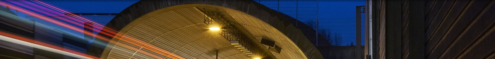
Blanka complex of tunnels in Prague
BLANKA COMPLEX OF TUNNELS IN PRAGUE
Owner:
The City of Prague
Mariánské náměstí 2
110 01 Praha 1
Odbor městského investora Magistrátu hl. m. Prahy
Vyšehradská 51
128 00 Praha 2
Project manager (owner’s representative)
Inženýring dopravních staveb a.s.
Na Moráni 3
128 01 Praha 2
VIS a.s.
Bezová 1658
140 00 Praha 4
Project coordinator and design engineer for equipment
SATRA, spol. s r.o.
Sokolská 32
120 00 Praha 2
Design engineer
SATRA, spol. s r.o.
Sokolská 32
120 00 Praha 2
PUDIS a.s.
Nad Vodovodem 2/3258
100 31 Praha 10
METROPROJEKT Praha a.s.
I.P.Pavlova 2/1786
120 00 Praha 2
Contractor for civil works
METROSTAV a.s
Koželužská 5/2246
180 00 Praha 8
Contractor for equipment
ČKD PRAHA DIZ, a.s.
Kolbenova 499
190 02 Praha 9
Operator
Technická správa komunikací hlavního města Prahy
Řásnovka 770/8
110 15 Praha 1
![]()
The largest underground construction project which is currently being implemented in the Czech Republic is the Blanka complex of tunnels in Prague. This extensive construction is being built within the framework of the development of the north-western part of the City Circle Road (the inner circle), in the Malovanka – Pelc Tyrolka section. The total length of this section is 6.382km; the aggregate length of tunnels in this section reaches respectable 5.5km.
The section of the Prague City Circle Road which is being built passes through the urbanised environment of the central part of the city, found on the border of the historic core and also passing through the space of the natural monument of Královská Obora - Stromovka Park (Royal Deer Park). This is how the uninterrupted complex of tunnels originated. It comprises three tunnel sections, following one after the other without interruption, between the Malovanka grade-separated intersection (at the northern portal of the Strahov tunnel) and the Troja intersection (at the new Troja bridge across the Vltava). Viewed in the order from the western part of the City Circle Road, which has already been operated, there are the following sections:
- The Brusnice tunnel section – it leads from the northern portal of the Strahov tunnel, within the footprint of Patočkova Street, first through cut and cover tunnels. Beyond the intersection with Myslbekova Street, the route enters a mined section, which ends before the Prašný Most intersection, where it continues through cut and cover tunnels. The entire section is 1.4km long; mined tunnels will take 550m of this length.
- The Dejvice tunnel section begins at the Prašný Most grade-separated intersection and continues throughout its length through cut and cover tunnels, running within the footprint of Milady Horákové Street up to the space of the future U Vorlíků grade-separated intersection. The total length of this section is 1.0km.
- The Královská OboraTunnel section continues from the U Vorlíků intersection, first as a short cut and cover section in Letná, then as a mined section leading under existing buildings, Stromovka Park, a shipping canal, Císařský Ostrov island and the Vltava River. Another cut and cover section starts from the island, ending at the Troja portal. The total length of the section is 3.09km; 2230m of this length will be mined.
Engineering description
The road is designed as a dual carriageway throughout its length, with a separate double- to triple-lane tubes in each direction. The vertical alignment of the tunnels descends from the Malovanka intersection under the Vltava; then it ascends to the Troja portal. The maximum longitudinal gradient reaches 5%. The difference between the altitudes of the tunnel at the highest and lowest points amounts to 330m. The smallest radius of a horizontal curve on the main route is 330m. The width of traffic lanes is 3.5m throughout the section; the clearance profile is 4.8m high. The design speed is 70kph.
Geological conditions are relatively very complicated and quite variable for the whole project. The route of the tunnels passes through the so-called Prague Basin, which is a partial sedimentation space of the extensive Barrandian synclinorium, where the bedrock consists of a folded complex of aleuropelitic shales, greywacke, sandstones and quartzites of the Ordovician age. Younger geological formations are represented by Quaternary surface deposits. Regarding the composition, sandy shale with gravel, i.e. stones and boulders of various size and rubble prevail. The thickness of the Quaternary sediments even reaches 38m, but usually it is less than 15m.
Ground water mostly follows the surface of the bedrock; the water table depth under the ground surface ranges from 8 to 20m. The superficial deposit layers it the area of the Vltava River and adjacent river terraces are saturated, depending on the river surface level.
The maximum and minimum heights of the overburden of the mined tunnels are 44m and 8m respectively. The shallowest cover of the tunnel under the Vltava is 14.5m.
The whole Blanka tunnel complex consists of three basic design types: one mined tunnel system and two cut and cover tunnel systems.
The design of all mined tunnels requires double-shell lining to be built whilst using the NATM. The primary lining is in C20/25 shotcrete, with lattice girders prefabricated from reinforcement bars, welded mesh and rockbolts. The excavation sequence design mostly comprises a top heading, bench and invert (the so-called horizontal sequence). Additional measures are designed for critical sections, i.e. stabilisation grouting, micropile umbrellas, an invert in the top heading, modification of the excavation sequence or a combination of these measures. The thickness of the primary lining varies from 200 to 400mm, depending on the NATM excavation support classes and the dimensions of the excavated cross section. The excavated cross sectional areas of the double-lane tunnel and triple-lane tunnel are 119m2 and 173m2 respectively.
The mined tunnel waterproofing system was designed with respect to the fact that gravity drainage of the tunnels by permanent drains was impossible; it consists of a waterproofing membrane installed around the full circumference, external waterstops on joints and a grouting-monitoring system.
The final lining of mined tunnels will be a closed structure, of cast-in-situ reinforced concrete. Some parts of inner structures (the slab and walls carrying the roadway) will be constructed simultaneously with the final lining, which will be divided into the invert structure (the bottom and side blocks) and upper vault. The lining will be cast using C30/37-class concrete; the side blocks will be of C20/28 concrete. The minimum thickness of the final lining will be 450mm and 500mm for the double-lane and triple-lane tubes respectively. Welded mesh supplemented, according to the results of structural analyses, with strap pieces will be used for concrete reinforcement.
The cut and cover tunnel sections are divided, according to the engineering solution, into traditional cut and cover structures and cover and cut structures, which will be built using the so-called Modified Milan Method (the MMM).
The traditional cut and cover tunnels will always be built in open excavation boxes supported either by diaphragm walls, soldier beam and lagging walls or sheet piling walls; open trenches with sloped sides or anchored rock walls on the sides will also be used. The tunnel structure consists of a bottom slab, side walls and roof deck, or an upper vault. The walls and vault will be 800mm thick, the minimum thickness of the roof deck will be 1000mm. All structures will be cast in situ using C30/37-class concrete, only the bottom slab and the bottom of the utility duct will be of C25/30 concrete. Tie-up reinforcement consisting of loose bars will be used. This type of tunnel structures is mostly used in locations with a complex spatial arrangement (portal sections, intersections, underground structures). The waterproofing of these sections is provided by means of bentonite mats and composites, always combined with supplementary elements to improve the tightness of expansion and construction joints.
The MMM tunnels are designed for the locations where the spatial conditions are very difficult and locations where the time available for surface traffic restrictions must be minimised. The construction process comprises the installation of in-situ structural diaphragm walls from the terrain surface or from the bottom of a pre-excavated construction trench, which is provided with supports of its sides. Then the final roof deck structure (resting on the heads of the diaphragm walls) is cast on the levelled bottom of the construction trench. When the process of the initial roof slab concrete hardening is finished, the slab is backfilled. Thus surface finishes can be performed and the traffic can be reinstated. The excavation within the tunnel tube itself is carried out subsequently, when the whole section of these tunnels is finished. It is performed from the adjacent construction trench where the traditional cut-and-cover tunnels are to be built. The tunnels of this design have a common central wall, shared by the southern and northern tunnel tube throughout their length. The roof deck acts as a 2-span continuous slab. The cross section of the tunnel tube consists of a reinforced concrete bottom bracing slab, 800mm thick diaphragm walls keyed into good bearing ground and a reinforced concrete roof deck. The roof decks and diaphragm walls are of C30/37 class concrete, while the bottom bracing slab and the bottom of the utility duct are of C25/30 class concrete. The thickness of the roof deck depends on the overburden height; it ranges from 1000mm to 1300mm. The protection of the tunnel against ground water is provided by water retaining concrete, which is used for the load bearing structures, supplemented by elements ensuring the tightness of expansion and construction joints, including measures allowing the injection of grout into the joints.
The operating ventilation system which is designed for the Blanka tunnel complex takes advantage of the vehicle-induced piston effect and combines semi-transverse and longitudinal ventilation principles with local exhaustion or supply of air in a unidirectional tunnel. During common operation, air is supplied to the tunnel mainly through entrance portals in combination with local inlets installed along the tunnel. Polluted air is forcedly evacuated through four ventilation plants, which are transversally connected to the tunnel so that the amount of polluted air drawn from the exit portals is reduced as much as possible. A semi-transverse, forced evacuation system is designed for the extraction of heat and smoke during a fire event, consisting of nozzles installed in the vault of the mined tunnel at about 80cm spacing. In the cut-and-cover sections, smoke and heat are evacuated forcedly through local ventilation plants or through tunnel portals by means of jet fans.
The Blanka tunnel project comprises even other associated transport-related structures, such as, for example, the at-grade section of the City Circle Road in Troja, the so-called New Troja Bridge across the Vltava River, a pedestrian subway under Holešovice railway station in Partyzánská Street, a bridge over the Praha – Chomutov rail line in Svatovítská Street (the so-called Prašný Most), a concourse for Hradčanská metro station, two underground car parks, flood defence walls, pedestrian subways or linking intersections and cycle ways. The volume of organisational and engineering problems is even continually expanded as a result of the planning of new construction projects to be implemented in the close vicinity of the Circle Road route, which are connected with the Blanka tunnels in terms of the space, not in terms of investment costs. We can name above all the building for the National Library, the National Football Stadium or the development of the Prague - Kladno high-speed track with Dejvice railway station on it.
Geotechnical monitoring is another inseparable part of the construction of mined tunnels. The scope of types of measurements and types of data to be read, structures which will be affected, measurement stations, monitoring equipment etc. is, in the case of the Blanka tunnel, complex, unparalleled by any other construction project which has been completed in the Czech Republic. It is assumed that 26 basic types of measurements will be conducted, which are designed to secure the safe progress of the construction, to allow subsequent steps of the observational method to take place and to follow the process of the trial operation of the tunnel.
The construction of the whole tunnel complex started in April 2005, in the area of the future Malovanka grade-separated intersection; it is gradually gaining momentum even in other parts of the route. Construction work in Troja and Letná has been in progress since April 2007 and June 2007 respectively. The year 2008 will see the beginning of the work in Hradčanská Street and in the area between Myslbekova Street and Prašný Most. The total project investment cost set by the design amounts to about 25 billion CZK. The Blanka complex of Tunnels has been in operation since 19th Sebtember 2015.
Other information on the project is available on the project web pages www.tunelblanka.cz .![]()
![]()
![]()
![]()
![]()
![]()
![]()
![]()
![]()
![]()
Comprehensive tests in the Brusnice tunnel (photo courtesy of Jakub Karlíček)
![]()
Rearranging traffic signs (photo courtesy of Jakub Karlíček)
![]()
Initial minutes of traffic in the Blanka complex of tunnels (photo courtesy of Jakub Karlíček)
![]()