
Prackovice and Radejčín tunnels on the D8 motorway
Official project name:
D8 Motorway, construction lot 0805 Lovosice – Řehlovice, Part E: Prackovice tunnel,
Part F: Radejčín tunnel
Project owner:
Roads and Motorways Directorate of the CR
Contractor:
Prackovice tunnel
Sdružení D8 0805 SSŽ-MTS consortium
Contractor: Metrostav a.s., Division 5
Sub-contractors: Subterra, a. s.; Zakládání staveb, a. s.
Radejčín tunnel
Sdružení D8 0805 SSŽ-MTS consortium
Contractor: Metrostav a.s., Division 5
Sub-contractors: AZ sanace a.s., Klement a.s.
Designer:
Prackovice tunnel
Final design: Pragoprojekt, a. s.
Detailed design: Valbek, s. r. o.; Tubes, s. r. o.; FG Consult, s. r. o.
Radejčín tunnel
Final design: PUDIS, a. s.
Detailed design: Pragoprojekt, a. s.
Contractor for geotechnical monitoring:
Prackovice tunnel - AZ Consult, spol. s r. o.
Radejčín tunnel - AZ Consult, spol. s r. o.
Construction period:
according to the tender: Prackovice tunnel: 630 days (without tunnel equipment)
Radejčín tunnel: 753 days
Technical data:
Prackovice Tunnel
Basic data
The Prackovice tunnel is part of the D8 motorway, construction lot 0805 Lovosice–Řehlovice, which runs across the Protected Landscape Area of České středohoří (Czech Uplands). It is a double-lane, unidirectional, T 9.5m category tunnel structure of. Each direction of traffic has a separate tunnel tube. The left tube and right tube are 270m long and 260m long, respectively.
Horizontal alignment conditions: – horizontal curve radius in the RTT: R = 1,014.08m
– horizontal curve radius in the LTT: R = 986.08m
Longitudinal gradient: 3.2%
Excavated cross-sectional area: 108 –129m2
Cross-sectional area of complete tunnel: 72m2
Geotechnical conditions
The Czech Uplands is a volcanic mountain range, which originated during the Palaeogene Period, when volcanic centres broke through the Bohemian Cretaceous Plateau. The area was subsequently formed by extensive erosion activities. The volcanic bodies comprise numerous effusions and subsurface intrusions. From the petrographical point of view, basalts, trachytes and phonolites prevail there. In addition, tuffs, tuff agglomerates or even tuffites, clays and swelling clays are found there. The whole geological situation is complicated by intense tectonic activity.
Construction technique
Stabilisation of the Prague portal
The excavation of individual stages of the shelf for the Prague portal encountered decomposed tuffs, intensely loosened and weathered tuffs, basalt debris and weathered basalts with up to 5cm wide fissures filled with clayey matter.
The unfavourable stability-related properties and the disintegration of weathered tuffs and basalts into fragments required the stabilisation of the portal area by pre-tensioned anchors, dowels and reinforced shotcreet. The dowels had to be installed into an environment reinforced in advance by jet grouting. Without this measure the effective installation would not have been possible. Another supplementary stabilisation measure had to be implemented prior to the excavation of the tunnel tubes itself: double-tier canopy tube pre-support was installed above each tunnel tube.
The substantial discharge of vertical and horizontal loads acting within the rock mass, resulting from the excavation removing nearly 20,000m3 of rock from the space in front of the portal wall, led to extensive spatial deformations of the rock mass and the portal wall.
This was the reason why two stabilisation measures were implemented: the immediate placement of 500m3 of excavated material to the portal wall up to the top heading bottom level, designed to ensure initial settling of the deformations; a third tier of pre-stressed stranded anchors was installed subsequently at the level of the bottom of top headings of the tunnels. Additional two measures had to be carried out later: depositing ground to the portal wall designed to ensure rapid settling of deformations, which was followed by casting a large monolithic concrete block leaning against the central part of the portal wall. This block, which was founded on inclined micropiles, supported the rock pillar between the tunnel tubes horizontally and even effectively surcharged the bottom of the trench in front of the portal wall. The reason was that the character of the deformations measured on the wall, on the bottom of the trench and inside the ETT indicated the likelihood of the development of a cylindrical shear plane, threatening the external stability of the portal wall.
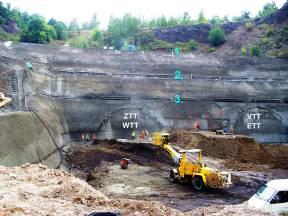
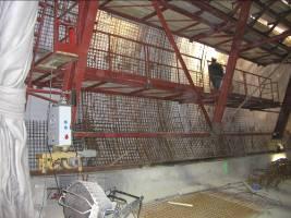
Prackovice tunnel – stabilisation of the Prague Prackovice tunnel - RTT upper vault waterproofing
portal and concrete reinforcement
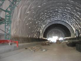
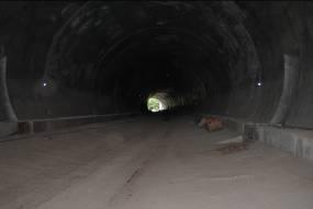
Prackovice tunnel – left tunnel tube – Prackovice tunnel - A view down the right tunnel
waterproofing by means of Junifol T membrane tube in the direction of Ústí nad Labem
Tunnel excavation; primary lining:
The tunnel excavation started from the southern mined portal (Prague portal), which had been stabilised in advance (structure SPO 601.01). Till that time an exploratory gallery with an access gallery (structure 601.00) had been completed.
According to the assessment of results of the geological survey and the condition of the rock mass which was to be encountered by the following tunnel excavation, the excavation was categorised as two excavation support classes: 4 and 5a. The lining of the mined tunnels has a reinforced concrete invert throughout the tunnel length.
The rock mass was disintegrated mechanically, only sporadically by drill and blast. The proportions of the disintegration operations were adapted to the conditions encountered during the construction, keeping to the NATM principles.
A double-tier canopy tube pre-support was installed above the contour of the upper vault of the future tunnel. The shape of the canopy allowed for the enlarged tunnel profile, required because of the fact that the thickness of the lining of the cut-and-cover tunnel in the location where the tunnel intersected with the portal wall was increased relative to the lining thickness in the mined part.
The construction started by erecting a protective collar (pre-shield) formed by a reinforced concrete shell having the shape of the tunnel lining designed for the NATM class 5a. The total length of the collar (pre-shield), including the keying into the portal slope, was about 4.5m at the Prague portal and about 3.5m at the Ústí nad Labem portal. The first step comprised the part of the collar set in front of the portal slope, up to the top heading level. The embedment of the collar was carried out only during the excavation of the bench and invert.
The protective collar itself consisted of SBT 1 lattice girders, which were fixed around the circumference by spacers. The lattice girders consisted of nine parts (including the parts for the invert). The parts were connected using bolted joints, with four bolts M20 with washers passing through butt plates. The butt plates were made from L 120/80/8 rolled-steel sections cut on the inner side of the girder so that they did not interfere with the installation of welded mesh and did not form irregularities when covered with shotcrete. Identical butt plates were at the end of the straight bottom elements of the pre-shield. They allowed the insertion of levelling plates or concrete padding when the levels of the girders were being adjusted. The components of the invert inside the tunnel tube beyond the pre-shield were connected by means of a spacing element comprising threaded rods. The shotcrete was reinforced by two layers of steel mesh ø6/100x6/100mm. Geotextile or wire fabric was fixed to the external surface of the girder, making the application of a 30cm thick layer of C20/25-XO shotcrete, forming the shell, possible from the collar interior. The external surface of the collar part embedded into the portal slope and the bottom part of the collar was vertical down from the springing of the tunnel vault (i.e. without rounding the bottom) with the aim of ensuring static stability of the loose part of the collar. In the case of necessity the pre-shield bottom was provided with an invert with the shape identical with the shape of the adjacent part driven through excavation support class 5a. The portal slope covered with shotcrete was broken away inside the tunnel excavation profile as the protective collar construction proceeded.
Secondary lining
Casting of concrete was divided into 16 blocks and 16 blocks for the left tunnel tube and the right tunnel tube of the mined part of the Prackovice tunnel respectively.
The casting blocks were 10m long. They were separated by transverse inter-block joints. An expansion joint was installed at the transition between the cut-and-cover and mined tunnel. It is 20mm wide and filled with extruded polystyrene.
The internal dimensions of the basic profile are uniform throughout the tunnel length: the net width of the final lining of 12.27m, the net height on the tunnel centre line of 9.10m, the height over the roadway of 7.10m. The minimum thickness of the final lining upper vault is 42.0cm at the tunnel crown, the minimum thickness of the invert is 72.0cm.
The reinforced concrete structure of the invert in the mined tunnel section is in C 25/30 XA1 concrete, reinforced with R 10 505.9 steel grade bars; the reinforced concrete structure of the upper vault in the mined tunnel section is in C 25/30 XF4, XD3 concrete, reinforced with R 10 505.9 steel grade bars.
The invert was cast on the primary lining invert, which was levelled and smoothed by C 12/15 X0 blinding and levelling concrete where necessary.
When casting of the invert and the installation of the upper vault waterproofing had been completed, the upper vault was cast using a 10.0m long steel form.
The concrete casting operations proceeded in the direction opposite to the direction of the chainage of the tunnel centre lines and the motorway alignment. The following procedure of the construction of the invert and upper vault in the mined tunnels was applied:
a) treating the foundation base by C 12/15 X0 blinding concrete and levelling concrete
b) installing external longitudinal drains and backfilling them with porous concrete
c) applying the waterproofing to the side-wall parts of the tunnel
d) placing reinforcement bars for the invert and casting of the invert of the tunnels
e) applying the upper vault waterproofing
f) placing reinforcement bars for the upper vault and casting of the upper vault.
Individual blocks of the upper vault formed separate rings. The reinforcement bars of the invert extended to the upper vault to be connected with its reinforcement. The upper vault was cast in 10m long blocks. The traveller formwork moved on rails installed on benches formed by the invert. Concrete was pumped behind the formwork through a pipeline; the level of the concrete surface was checked on both sides of the formwork through checking gates in the formwork.
When the concrete invert was being cast, measures were executed in the locations of recesses (openings for the connection between sewerage manholes and longitudinal drainage, opening in the bottom for the connection of the longitudinal drainage in the cross passage and the manhole on the tunnel side drainage, and the space for flame-retardant pieces of slotted drains and openings for hydrants on the fire main).
The waterproofing system was installed and concrete reinforcement was placed prior to the casting of the particular upper vault block.
The expansion joint between blocks at the interface between the mined part and the cut-and-cover part was filled with 20mm thick extruded polystyrene. On the internal surface, the joint was sealed by an acrylate fire-proofing compound up to the depth of 20mm. The exposed joint was treated by inserting a trapezoidal profile into it. The waterproofing layer thickness was increased around the joint in the vault by adding a 600mm-wide strip and a profiled waterstop was installed in the middle of the lining thickness.
Tunnel drains with the inner diameter DN 200mm were installed on the external side of the mined tunnels. The pipes are circular in the basic profile, with perforation in the upper part. The perforated design is changed to a circular profile without perforation at passages through the bottom lining. Inside the passage opening itself, a sealing flange preventing water from seeping to the inner surface of the tunnel lining was glued to the drainage pipe, approximately in the middle of the lining thickness.
The drainage pipeline was carried out using DN200 pipes with SN10 circular strength. The external drainage was backfilled with porous concrete.
The waterproofing system consisted of a 2.5mm thick LLDP membrane with a signal layer and GEOFILTEX 500g/m2 - B2 geotextile (on the inner surface of the primary lining vault).
When the drainage placement had been finished, one 2.0m-wide strip of the membrane was applied longitudinally on both sides of the tunnel, up from the porous concrete bottom. This operation had been carried out before the reinforcement of the invert was installed and the invert was cast. The remaining part of the waterproofing was applied after the invert casting had been completed. The membrane mats applied in the direction transverse to the tunnel centre line were connected to the longitudinal strip on the side wall. The mats were connected by means of double-seam welds.

Prackovice tunnel – Right tunnel tube, the upper vault casting finished
Radejčín Tunnel
Basic data
The Radejčín motorway tunnel passes under the flat Radejčín Ridge, which is part of the Bohemian Uplands, east of the Radejčín railway station. A separate tunnel tube was designed for each direction of the dual carriageway. The tunnel is designed as a T 9.5 category structure (double-lane, unidirectional) with the two separate tubes driven at the maximum distance between centres of 28m. The right tunnel tube is 600m long; 446m of this length are built by a mining technique. The left tube is 620m long; 446m of this length are built by mining methods.
Horizontal alignment conditions: the tunnels are straight
Gradients: longitudinal gradient of 2.4% up to 0%, transverse gradient of 2.5% falling toward the right-hand shoulder
Excavated cross-sectional area: 108 –129m2
Cross-sectional area of complete tunnel: 72m2
Geotechnical conditions
The geological conditions encountered can be uniformly summarised as a volcano-sedimentary complex of Miocene tuffs and basic effusive rock types, with markedly developed bedding and variable thickness of individual sets of beds. The thickness of the beds varies within the range of tens of centimetres up to a metre.
The tuffs contain altered and tectonically disturbed layers of the cohesive soil character.
Basalt, unweathered up to technically sound, is another important rock type. It was encountered first of all during the course of the excavation of the tunnelled sections, but also during the excavation of the trench at the Ústí nad Labem portal.
Construction technique
Underground excavation
The tunnel has been driven using the NATM, through rock mass categorised as classes 3, 4, 5a and 5b, with the classes 5a and 5b requiring reinforced concrete invert in the primary lining.
Drill-and-blast is the most frequently used rock disintegration technique in the tunnels, with the exception of the beginning of the excavation, where a tunnel excavator was used for the mechanical disintegration at the tunnel portal. The round lengths designed for the individual excavation support classes in the top heading is 1 – 1.5m for class 5a and 1.2 – 1.8m for class 4. In the bench, the round lengths varied from 2 to 4m for class 5a and from 3 to 5m for class 4. The bench excavation has been carried out using two systems: either with the bench face excavation divided into halves concurrently with the top heading excavation or the full-face excavation, suspending the work on the tunnel top heading.
The bottom excavation and construction of the invert follow after the bench excavation, with the round lengths of 2-4m for class 5a and 3-5m for class 4 (see Fig. 5).
The following NATM means of support were used:
· C 20/25-X0 shotcrete, 300-200mm thick (the wet process)
· KARI KY50 8/150 x 8/150mm mesh for the outer-side layer
· KARI Q188A 6/150 x 6/150 mesh for the inner-side layer
· BTX lattice girders
· IBO self-drilling, groutable bolts 4 – 6m long (as required)
· Hydraulically expanded rock bolts 4 – 6m long
Shotcrete and dowels (32mm in diameter, spaced at 35cm) are applied to the top heading.
In the cases of exceptionally unfavourable geology, 6m long anchors are installed into the excavation face, mostly of the self-drilling IBO type.
Another top heading stabilising element was the use of spread footings for three excavation support classes: 4, 5a and 5b.
Secondary lining
Casting of concrete is divided into 45 blocks in the left tube and 45 blocks in the right tube of the mined part of the Radejčín tunnel. The sequence of the marking of the blocks is in the direction contrary to the direction of tunnel chainage. It follows the direction of the concrete casting sequence, i.e. from the Ústí portal toward the Prague portal.
The tunnel blocks are 10m long. They are separated from each other by transverse joints. An expansion joint is at the interface between the cut-and-cover and mined tunnel. It is 20mm wide and filled with extruded polystyrene.
The reinforced concrete structure of the invert (blocks) in the mined part of the tunnel is in C 25/30 XA1 concrete, reinforced using steel grade R 10 505.9, whilst the reinforced concrete structure of the upper vault in the mined part is in C 25/30 XF4, XD3 concrete, using steel grade R 10 505.9.
The invert is cast on the primary lining invert, which is treated and levelled with C 12/15 X0 blinding concrete and levelling concrete as required.
When casting of the invert and the installation of the upper vault waterproofing has been completed, the upper vault is cast using a 10.0m long steel form.
The concrete casting operations proceed in the direction opposite to the direction of the chainage of the tunnel centre lines and the motorway alignment. The following procedure of the construction of the invert and upper vault in the mined tunnels is applied:
a) treating the foundation base by blinding concrete and levelling concrete C 12/15 X0
b) installing external longitudinal drains and backfilling them with porous concrete
c) applying the waterproofing to the side-wall parts of the tunnel
d) placing reinforcement bars for the invert and casting of the invert of the tunnels
e) applying the upper vault waterproofing
f) placing reinforcement bars for the upper vault and casting of the upper vault.
Individual blocks of the upper vault form separate rings. The reinforcement bars of the invert extend to the upper vault. The upper vault is cast in 10m long blocks. The traveller formwork moves on rails installed on benches formed by the invert. Concrete is pumped behind the formwork through a pipeline; the level of the concrete surface is checked on both sides of the formwork through checking gates in the formwork.
When the concrete invert is being cast, measures are executed in the locations of recesses (openings for the connection between sewerage manholes and longitudinal drainage, opening in the bottom for the connection of the longitudinal drainage in the cross passage and the manhole on the tunnel side drainage, and the space for flame-retardant pieces of slotted drains and openings for hydrants on the fire main).
The waterproofing system is installed and concrete reinforcement is placed prior to the casting of the particular upper vault block.
The expansion joint between blocks at the interface between the mined part and the cut-and-cover part is filled with 20mm thick extruded polystyrene. On the internal surface, the joint is sealed by acrylate, fire-proofing compound up to the depth of 20mm. The exposed joint is treated by inserting a trapezoidal profile into it. The waterproofing layer thickness is increased around the joint in the vault by adding a 600mm-wide strip; a profiled waterstop is added to the middle of the lining thickness.
Tunnel drains with the inner diameter DN 200mm are installed on the external side of the mined tunnels. The pipes are circular in the basic profile, with perforation in the upper part. The perforated design is changed to an non-perforated circular profile at passages through the bottom lining. Inside the passage opening itself, a sealing flange preventing water from seeping to the inner surface of the tunnel lining is glued to the drainage pipe, approximately in the middle of the lining thickness.
The drainage pipeline is carried out using DN200 pipes with SN10 circular strength. The external drainage is backfilled with porous concrete.
The waterproofing system consists of a 2.5mm thick LLDP membrane with a signal layer and GEOFILTEX 500g/m2 - B2 geotextile (on the inner surface of the primary lining vault).
When the drainage placement is finished, one 2.0m-wide strip of the membrane is applied longitudinally on both sides of the tunnel, up from the porous concrete bottom. This operation is carried out before the reinforcement of the invert is installed and the invert is cast. The remaining part of the waterproofing is applied after the invert casting is completed. The membrane mats applied in the direction transverse to the tunnel centre line are connected to the longitudinal strip on the side wall. The mats are connected by means of double-seam welds.
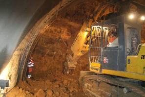
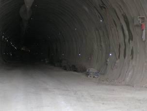
Radejčín tunnel – Ground disintegration at the face Radejčín tunnel – Left (southern) tunnel tube
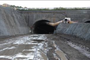
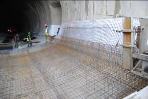
Radejčín tunnel – the Ústí portal, a view of the Radejčín tunnel – Placement of reinforcement
right (northern) tunnel tube of the invert in the mined part – the Ústí portal
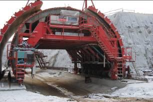
Radejčín tunnel – Formwork for casting of the upper vault